CAN & CAN FD
Table of Contents
1 Introduction
2 CAN Data Frame
3 Bit Time Calculations
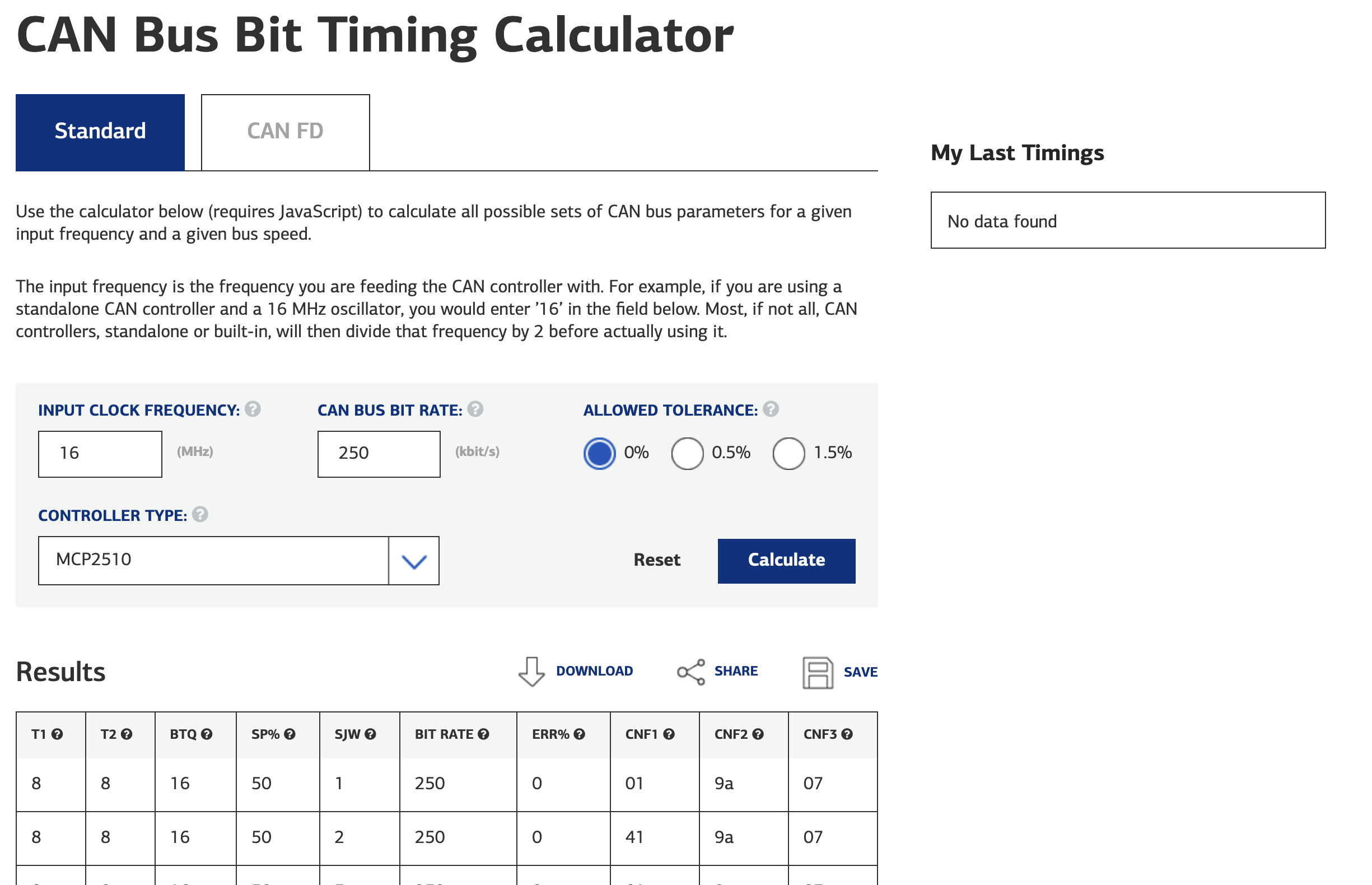
3.1 Kvaser Bit Timing Calculator
Kvaser has a well-built public use CAN and CAN FD bit timing calculator:
The following calculation steps will be based off this resource. However, these calculations could be done on many other calculators and by hand.
3.2 CAN Bus Bit Timing Calculation Steps
3.3 CAN FD Bus Bit Timing Calculation Steps
3.3.1 CAN Bus Device Characteristics
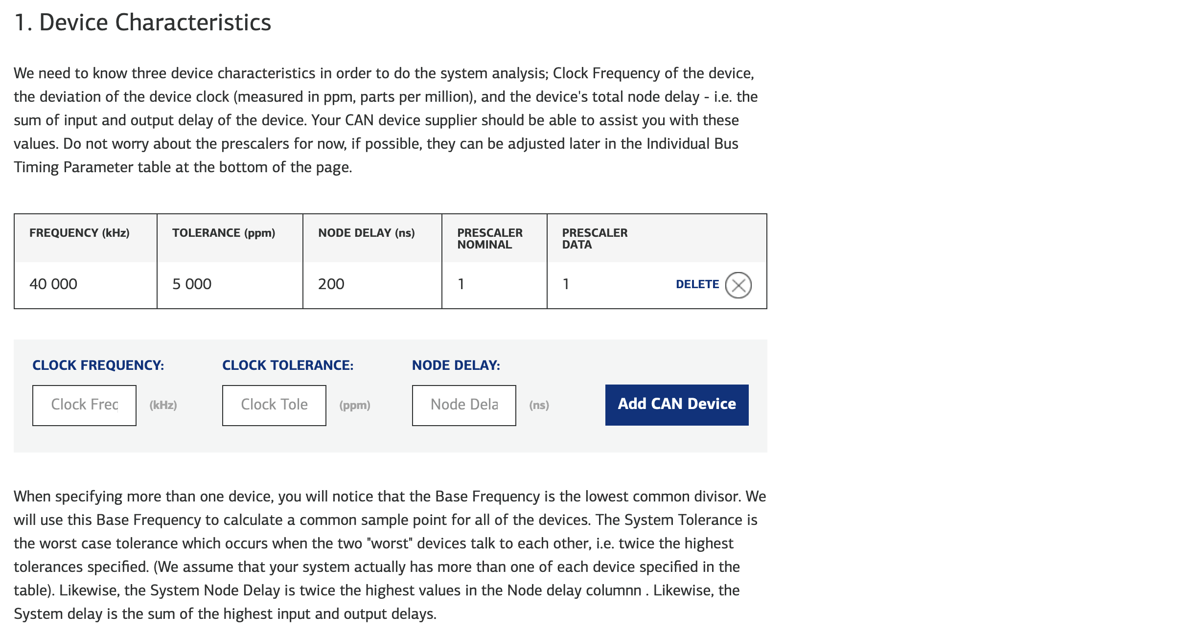
Clock Frequency: Clock frequency at which the device's CAN FD peripheral is running at. Specified by your MCU configuration.
Clock Tolerance: Tolerance of the device's actual input clock. Commonly found on MCU or crystal oscillator datasheet.
- Percent tolerance: $%{tolerance} = \frac{f{max} - f_{typ}}{f_{typ}} \times 100$
- Parts per million (ppm) tolerance: $ppm_{tolerance} = %_{tolerance} \times 10000$
Node Delay: (Aka propagation delay) Sum of the device's input and output delay. Commonly found on the CAN FD transceiver datasheet.
- Note this may vary depending on the load / terminating resistor used.
- If you are unsure, the general recommendation is to use the maximum delay.
3.3.2 Nominal and Data Bitrates
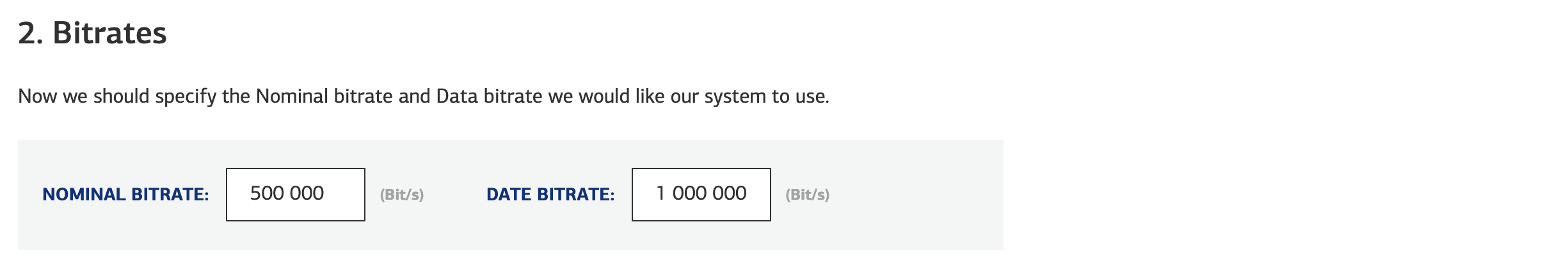
Nominal Bitrate: Bitrate used during the arbitration phase of CAN communication. 500 kHz is used here as it is the traditional bitrate used in classic CAN systems. This phase is critical for ensuring that the message with the highest priority (lowest identifier) is transmitted first.
Data Bitrate: CAN FD introduces the concept of a higher data bitrate, which is used during the data phase of CAN communication. This allows for much faster data transmission rates than the nominal bitrate, which is especially useful for transmitting larger data payloads allowed by CAN FD.
The reason for the two different bitrates is to maintain compatibility with older CAN networks and to enhance efficiency. The arbitration phase is kept at a lower bitrate to ensure robustness and compatibility with classic CAN systems, while the data phase can take advantage of the faster speeds to improve data throughput. This dual-rate system is what allows CAN FD to be more efficient and to carry more data without sacrificing the reliability and deterministic nature of traditional CAN bus networks.
3.3.3 Sample Point
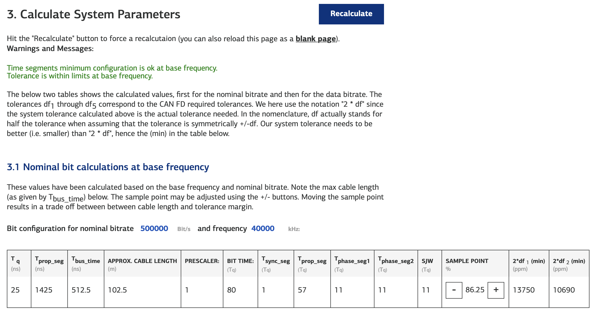
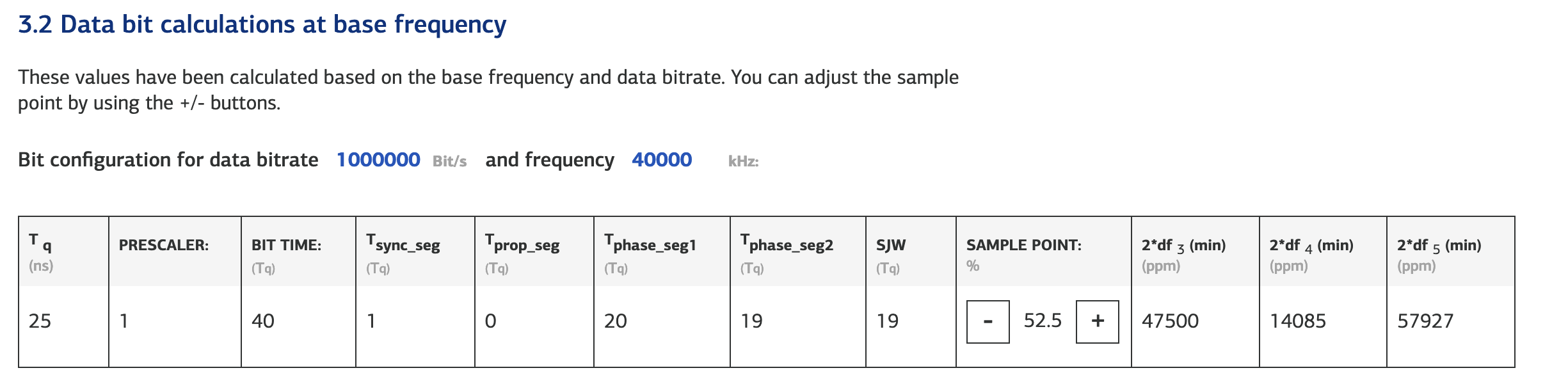
Sample Point: The point in time, as a percentage of the total bit time, at which the CAN controller samples a bit on the CAN bus during a message frame.
Proper configuration of the sample point is crucial because it must account for signal propagation delays across the network and phase shifts in the oscillator clock of the various nodes to ensure reliable communication. In other words, these values allow for some level of delay while still sampling the bit before the end of the bit time.
Recommended values:
- Classical CAN:
~75% to 90%of the bit time. - CAN FD:
~70% to 80%of the bit time.
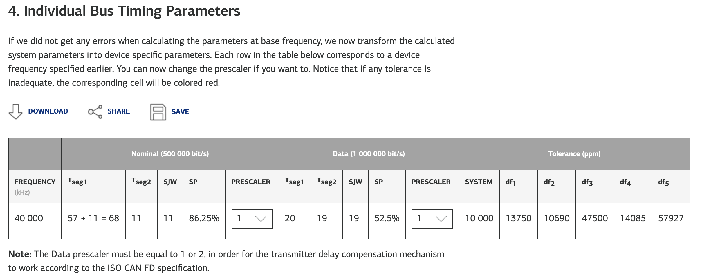
3.3.4 Individual Bus Timing Parameters